Solid-Liquid suspension (slurry) : an overview
Powder liquid mixing
Follow us on Twitter ![]()
Question, remark ? Contact us at admin@powderprocess.net
| Section summary |
|---|
| 1. Introduction |
| 2. Settling of suspension |
| 3. Rheology of a slurry |
| 4. Pipe flow of solid-liquid suspension |
| 5. Powder liquid mixing process and equipment |
1. Introduction
The use of liquid-solid suspension - also called slurry or colloids depending on the size of particles dispersed and the tendency to sediment - is common in process industries. Such suspension can for example be found at the very beginning of a process, after a liquid and a solid have been contacted in a reactor or mixer.
There can be different reasons to their use. It can offer an easier handling of the solid, for example, or be made necessary to obtain certain chemical reaction, or certain physical interaction, like the trapping of some aroma of the solids in the liquid.

Although found quite commonly in process industries, those mixtures are nevertheless posing different challenges, especially in terms of rheology where they have most of the time a behavior that is not newtonian.
This page aims at giving to the reader different tools to help manage industrial situations with liquid-solid slurry.
2. Settling of suspension
At what velocity particle settle down ?
One of the 1st challenges when handling a slurry is to avoid that the particles settle and that 2 phases reconstitute. Slurry sedimentation can be a problem and it is advisable to assess the speed at which the slurry can sediment. It will give an idea of the stability of the suspension and of the efforts that will have to be considered during the design to prevent the settling.
The most direct method is carry out a test at pilot plant scale. However, such test is not always available, thus some calculation can also be done.
Calculations actually come from a force balance on a particle settling in the slurry.
A simple method is given below - valid for a single spherical particle
Top
5 Most Popular
1.
Pneumatic transport design guide
2. Ribbon blenders
3. Powder mixing
4. Hoppers design guide
5. Measuring degree of
mixing
--------------
 --------------
Top 5 New
1. Continuous Dry Mixing
2. Mixing speed
3. Mixer cycle time
optimization
4. Batch
/ continuous mixing comparison
5. Energy Savings
Terminal settling velocity is :
![]()
Equation 1 : Terminal settling velcity of a single particle
With the following nomenclature
s=(ρp/ρ) - specific density of the particle in the
fluid carrier
g=gravitational constant (ms-2)
CD=Drag coefficient (-)
dP=Diameter of particle (m)
The drag coefficient can be calculated depending on the values of the Reynolds particles.
In laminar
regime (Rep<2)
CD=24/Rep
Equation 2 : Drag coefficient of particle in laminar regime
In transition regime (2<Rep<500)CD=18.5/Rep0.6
Equation 3 : Drag coefficient of particle in transition regime
In turbulent regime (500<Rep<20000)CD=0.44
Equation 4 : Drag coefficient of particle in turbulent regime
The Reynolds particle can be calculated directly as a function of the Archimede number following

Equation 5 : Reynolds of particle
The value obtained for a single particle is actually greater than the actual velocity observed in a slurry, the different particles interacting between each other, which is reducing the settling speed. A method is proposed by Oroskar and Turian to account for this effect. The terminal settling velocity can be corrected the following way.
Vsh=Vs(1-cv)n
Equation 6 : Terminal settling velocity
With the following notation :
cv=% volumetric concentration of solids in slurry
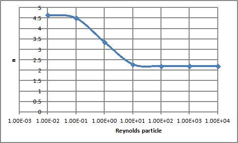
n is a power number function of the Reynolds particle

Figure 1 : n factor as a function of the Reynolds
Note : other correlations can be found in Mecanique et Rheologies des Fluides, Midoux, Lavoisier Tec et Doc, 1993, page 386
Now, knowing the speed at which the suspension will settle is of help in order to design the process. However, it does not answer the following question : when pumping the suspension into a pipe, will the suspension separate and 2 phases will finally appear. As a rule of thumb, it is found in literature that problem will appear for suspension with a low level of solid (<25% volume) for which the viscosity is low and therefore the settling quick and / or with large particles (>100 microns).
The critical velocity in pipe under which phase separation can happen can be evaluated thanks to the following equation (Hanks 1986) :
![]()
Equation 7 : Critical pipe velocity
With the following parameters :
cv=% volumetric concentration of solids in slurry
s=(ρp/ρ) - specific density of the particle in the
fluid carrier
3. Rheology of liquid-solid suspensions - Viscosity of a slurry
What is the viscosity of a colloidal suspension ?
The rheology of a slurry can be quite complex since in most of the cases, the rheology will not be Newtonian.
A Newtonian fluid is characterized by a viscosity that is independent of the shear rate. It is the case of water for example, and many other pure substances. Slurries, on their side, can present a viscosity that will change with the shear rate.
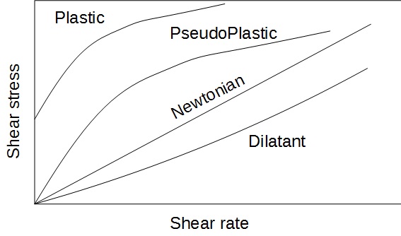
The different types of behaviors of a particle suspension that can be found is represented on the following drawing. The shear stress is shown as a function of the shear rate. As reminder, the dynamic viscosity is defined as the ratio shear stress / shear rate

Figure 2 : Rheological behaviors
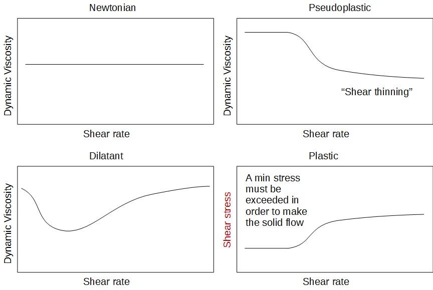
The different behavior can be better visualized by plotting the dynamic viscosity as a function of the shear rate.

Figure 3 : Rheological behaviors - Dynamic viscosity = f(shear rate)
A very common situation for a slurry is to behave according to the pseudoplastic behavior, which means that the liquid will be shear thinning. It presents some advantages since the pressure drop will be less high in the pipes. It should however guide the choice for the pumping equipment for these fluids, a positive displacement pump is indeed probably a better choice than a centrifugal pump in which the viscosity may decrease a lot, preventing the pump to push the fluid in the pipe downstream.
A last rheological phenomenon is worth mentioning : the thixotropy and antithixotropy. Basically, there is a time hysteresis in the viscosity observed. A typical example of thixotropy are paints : agitating the paint will quickly reduce dramatically the viscosity, however, when stopping to agitate, the viscosity will increase again but slowly, giving time to use a very liquid paint.
4. Pipe flow of solid-liquid suspension
What is the viscosity of a particle suspension ?
Due to their non-newtonian behavior, slurry handling is often a challenge. Different rheological models are available to describe the flow properties of solid liquid suspensions : Power law (Ostwald de Waele), Bingham, Casson, depending on the actual viscosity behavior.
In practice, a Power Law can be fitted in different parts of the viscosity plot as a function of the shear rate.
The law is in the following format :

Equation 8 : Viscosity powder law
What is important here, from the experience, if to calculate the exponent n.
The Reynolds number as well as the friction factor can then be calculated.
Laminar flow
To be updated soon
Turbulent flow
To be updated soon
5. Solid-Liquid Mixing process and equipment
Creating the suspension is the 1st step in a process handling a slurry, which requires a liquid-solid mixing step. Typically, an agitated tank (see figure 1) is used as solid liquid blender although other types of solid liquid mixing equipment exist (inline mixer for example). The type of agitator is important as well as the determination of the agitation speed necessary to mixing solid-liquid suspensions and maintain the particles in suspension.
An agitator performing a high shear is advised for contacting the solid and the liquid (typically a turbine with 45 degrees blades). It helps creating the turbulence necessary to overcome the settling of particles and can also help to break some aggregates that may be created.
If the suspension is very homogeneous, then this agitator can then be relayed by another one rotating slower (anchor), if the suspension is settling very quickly, it is probable that it is necessary to keep the turbine on.
What is the minimal agitation speed for a liquid solid suspension ?
In order to determine the minimal agitation speed for having a suspension, the literature is often referring to the correlation of Zweitering (1958)

Equation 9 : Minimum agitation speed to put solids in suspension
With the following nomenclature
S=Zweitering coefficient, a function of the system geometry
ν=μ/ρ the slurry kinetic viscosity (m2.s-1)
dp=the particle diameter (m)
δρ=the difference between volumic weight of particle and of liquid
abs(ρp-ρl) (kg/m3)
Di=agitator diameter (m)
X=mass solid concentration (% weight - please use percentage in
the formula)
The values for S can be found in the litterature from different
authors and for different agitators. Below are the values from
Armenante et al (1988)

Equation 10 : Zweitering Coefficient
Table 1 : Parameters for Zweitering Coefficient Calculation
| Coefficient | Disc Turbine vertical blades, rushton type (TPDD) | Turbine 6 vertcial blades (TPP) | Turbine 6 blades tilted, low pumping (TPIB) | HE3 Chemineer |
|---|---|---|---|---|
| A | 0.99 | 1.43 | 2.28 | 3.49 |
| a | 1.40 | 1.20 | 0.83 | 0.79 |
| b | 2.18 | 1.95 | 0.65 | 0.66 |
HA is the height from the bottom of the tank to the
agitator (m)
D is the diameter of the agitator (m)
T is the diameter of the tank (m)