
Hopper Design - Flow of Powder & Discharge
Hopper / Silo Design Calculation Method & Interactive Tool
| Don't want to design ? Do you want to solve a discharge problem in your silo ? If yes, access our HOW TO : How to solve flow problems ? |
Follow us on Twitter

Question, remark ? Contact us at admin@powderprocess.net
| Section summary |
|---|
| 1. Silo / Hopper Design Calculation Methods (Jenike & Beverloo) |
| 2. Interactive Silo Sizing Calculator (#calc-app) |
| 3. Discharging Aids & Air Balancing |
| 4. Engineering Best Practices & Rules of Thumb |
What this page is about
Powder handling processes are made of many unit operations, some complex, some that can seem easier. Discharging powder is often overlooked, however, issues in this a priori simple operation can lead to huge losses.
Discharging powder must be
- Reliable
- Fast enough
- Controlled

The performance of an industrial process will be judged, among other parameters, according to its capacity to reach a nominal speed (expressed in terms of throughput, cycle time or number of batches / h). If a hopper which is supposed to deliver powder at a given rate cannot do it, be it placed at the beginning, middle, or end of the process, the whole installation "speed" will be affected.
This page will allow you to :
- Design a silo / hopper in order to ensure a good flow
- Estimate the discharge rate of a silo / hopper
- Take action in case of flow problems
Note that the way a powder is flowing depends on its properties. General powder properties, including flow properties, are listed in this page : Powder Properties.
1. Silo / Hopper Design Calculation methods
1.1 Why it is important
Powder has a given ability to slide and fall when it is stored in a hopper. A key variable that will have an impact on the flow of product outside of a bin is its cohesive strength.
In a bin, the powder is submitted to pressure, due to the height of powder in the bin pushing on the powder below. Due to this pressure, some solids tend to become more cohesive, forming arches or ratholes—two phenomena very detrimental to gravity discharge.
However, the stress (pressure) profile in a bulk solid silo is fundamentally different from hydrostatic liquid pressure.

Figure 1 : Stress profile in bulk solids silos (Janssen effect)
The powder is consolidated in the top cylinder section due to Janssen stress saturation. In the hopper cone, the consolidating stress decreases, minimizing the forces driving gravity flow: arching (cohesive bridging) can thus occur. Proper design finds the hopper angle and outlet diameter necessary to maintain stresses high enough to break arches and establish reliable mass flow.
Table 1 : Key Silo Design Parameters
| Key silo design parameters |
|---|
| Discharge diameter (avoids arching and ratholing) |
| The discharge angle (cone/wedge half-angle) |
| The working volume of the silo |
| The gravity discharge rate from the silo |
1.2 Calculating the silo discharge diameter with the method of Jenicke
The flow of powder in a hopper is linked to 3 core shear properties:
- Internal friction angle (\(\phi_i\)): Resistance of powder particles to move relative to each other.
- Wall friction angle (\(\phi_w\)): Friction between powder particles and the internal silo wall lining.
- Compressibility & Flow Function (FF): Unconfined yield strength (\(f_c\)) developed as a function of major consolidating stress (\(\sigma_1\)).
STEP 1 - Get information on the powder
Measure the Powder Flow Function, wall friction angle, and internal friction angle using a Jenike or rotational shear tester.
STEP 2 - Calculate the hopper angle for mass flow
Determine the maximum hopper wall slope angle (\(\theta\)) to guarantee mass flow using Jenike's design charts based on wall friction (\(\phi_w\)) and internal friction (\(\phi_i\)). Apply a safety margin of \(3^\circ\) to \(5^\circ\).
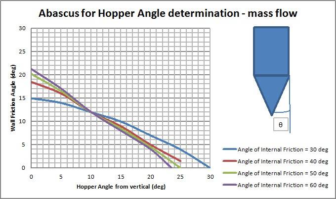

Figure 2 : Abacus for discharge hopper angle calculation [1]
STEP 3 - Calculate the flow factor (FF)
Read the Hopper Flow Factor (\(ff\)) from Jenike design abacuses using the selected hopper angle (\(\theta\)) and wall friction angle (\(\phi_w\)).
For cone shaped hopper  |
For wedge shaped hopper  |
Figure 3 : Abacus for flow factor calculation [2]
STEP 4 - Calculate the critical cohesive strength (\(f_{c,\text{crit}}\))
Plot the Flow Factor line (\(\sigma_1 / ff\)) over the Powder Flow Function curve. The intersection defines the critical unconfined yield strength \(f_{c,\text{crit}}\).

Figure 4 : Flow Function and Material Flow Functions to calculate Critical Applied Stress
STEP 5 - Calculate the parameter H(\(\theta\))
Determine the dimensionless parameter \(H(\theta)\) from Jenike's abacus as a function of the hopper half-angle \(\theta\).
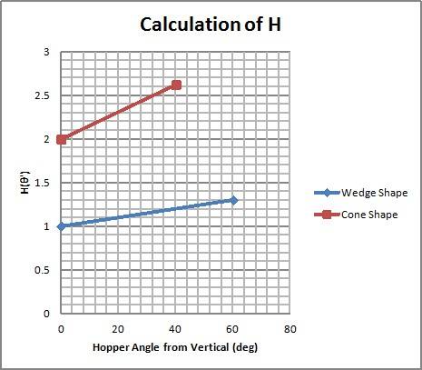
Figure 5 : Abacus for H parameter calculation (Red: axisymmetric cone, Green: planar wedge)
How to calculate the outlet diameter of a silo?
STEP 6 - Calculate the critical outlet diameter to avoid bridging (arching)
The minimum outlet dimension \(d_{\text{crit}}\) to prevent cohesive arching is calculated via Equation 1:
\[ d_{\text{crit}} = \frac{H(\theta) \cdot f_{c,\text{crit}}}{g \cdot \rho_b} \]
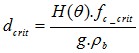
Equation 1 : Critical outlet diameter to avoid cohesive arching [2]
Where \(\rho_b\) is bulk density under consolidation, \(g = 9.81\text{ m/s}^2\), \(H(\theta)\) is the geometry factor, and \(f_{c,\text{crit}}\) is critical yield strength.
STEP 7 - Calculate the critical rathole diameter
For funnel flow silos, the minimum opening diameter to prevent stable ratholing is calculated via Equation 2:
\[ d_{\text{rathole}} = \frac{G(\phi) \cdot f_c}{g \cdot \rho_b} \]
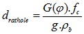
Equation 2 : Critical outlet diameter to avoid ratholing [2]
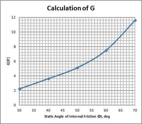
Figure 6 : Abacus for G parameter calculation
1.3 Types of bins
The primary bin flow patterns encountered in bulk materials storage are:
- Mass Flow Bin: Material is in motion at every point along the hopper walls during discharge. First-In, First-Out (FIFO) discharge. Prevents ratholing and minimizes caking.
- Funnel Flow Bin: Material flows through a central core over stagnant material near walls. First-In, Last-Out (FILO). Prone to ratholing and erratic flooding.

Figure 7 : Bin discharge patterns
1.4 Feeders used at discharge of hopper
Feeders regulate powder flow leaving the silo. Common options include screw feeders, airlock rotary valves, vibrating feeders, and butterfly valves.
Table 2 : Feeder design considerations
| Feeder Type | Specific Engineering Precautions |
|---|---|
| Screw feeder | Use variable pitch or tapered flights across elongated outlets to ensure uniform powder draw down along the entire length [3]. |
| Airlock rotary Valve | Install a vertical spool piece (~2 pipe diameters) between hopper cone and valve inlet to stabilize material velocity and vent leakage air. |
| Butterfly valve | Compact and hygienic. Disk restriction in flow stream may trigger arching in cohesive powders—vibrating disks or activation aids may be required. |
1.5 Calculation of the discharge rate
Coarse particles (\(d_p > 400\,\mu\text{m}\))
The Beverloo equation estimates the maximum gravity discharge rate through an orifice for coarse, free-flowing solids:
\[ W = C \cdot \rho_b \cdot \sqrt{g} \cdot (d_0 - k \cdot d_p)^{2.5} \]

Equation 3 : Beverloo equation for gravity discharge rate
- \(W\): Discharge rate (\(\text{kg/s}\))
- \(C\): Empirical discharge coefficient (\(0.55 \le C \le 0.65\), default \(0.58\))
- \(k\): Particle shape coefficient (\(1.0 \le k \le 2.0\), default \(1.6\))
- \(\rho_b\): Bulk density (\(\text{kg/m}^3\))
- \(g\): Acceleration of gravity (\(9.81\text{ m/s}^2\))
- \(d_p\): Particle diameter (\(\text{m}\))
- \(d_0\): Discharge orifice diameter (\(\text{m}\))
Johanson Equation:
\[ \dot{m} = \rho_b \cdot A \cdot \sqrt{\frac{B \cdot g}{2 \cdot (1 + m) \cdot \tan(\theta)}} \]
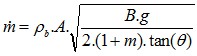
Equation 4 : Johanson equation for coarse particles
Fine particles (\(d_p < 400\,\mu\text{m}\))
For fine powders, interstitial air pressure gradients drastically reduce flow. The Carleton equation accounts for air drag resisting gravity discharge:
\[ \frac{4 V_0^2 \sin(\theta)}{B} + 15 \frac{\rho_{\text{air}}^{1/3} \mu_{\text{air}}^{2/3} V_0^{4/3}}{\rho_p d_p^{5/3}} = g \]
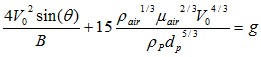
\[ \dot{m} = \rho_b \cdot A \cdot V_0 \]

Equation 5 : Carleton equation for fine powders
Interactive Silo & Hopper Discharge Calculator
Evaluate gravity discharge rates (Beverloo), minimum orifice sizing, and Jenike critical arching outlet limits in SI Metric or US Customary units.
2. Discharging aids
A good hopper design is the primary requirement for reliable flow. However, flow promotion equipment may be necessary when handling cohesive powders, materials subject to storage caking (e.g., sugar), or inside layout-constrained vessels.
Table 3 : Discharging aids summary
| Group | Discharging aid | Characteristics & Industrial Application |
|---|---|---|
| Mechanical | Agitator / Sweeper | Effective in smaller hoppers (e.g., Loss-In-Weight feeders). Requires careful mechanical design to withstand high bulk torque. Avoid in strict hygienic zones. |
| Mechanical | Lump breakers | Positioned below hopper outlets to de-agglomerate fragile lumps before entering downstream feeders. |
| Mechanical | Pneumatic Knockers | Delivers controlled impacts to clean vessel walls during batch discharge, preventing wall build-up. |
| Pneumatic | Fluidizing pads / Air Cannons | Injects compressed air along hopper walls to aerate powder and break cohesive bridges. Note: improper aeration in ratholing-prone materials can cause sudden flushing. |
| Vibration | Vibrating bottom (Bin Activator) | Suspended cone activated by unbalanced motors. Highly effective for non-compressible solids. Avoid for highly compressible powders to prevent compaction! |
| Material | Wall Linings / Polishing | Reduces wall friction angle (\(\phi_w\)) via electropolishing, PTFE, or UHMW-PE liners, widening the mass flow envelope. |
3. Air balancing
Air balancing during hopper discharge is essential—especially for precise loss-in-weight dosing. Discharging powder displaces air: negative pressures in the discharging silo impede gravity flow, while overpressures in receiving vessels create dust clouds and valve leakage.

Figure 8 : Pressure effects during powder discharge
Properly dimensioned vent filters or pressure-equalization lines between supply and receiving bins eliminate flow restrictions caused by vacuum locking.
4. Engineering Rules of Thumb & Safety Limits (E-E-A-T)
Industrial Silo Design Rules of Thumb
- Mass Flow Safety Margin: Always design the hopper wall slope angle \(\theta\) at least \(3^\circ \text{ to } 5^\circ\) steeper than Jenike's theoretical mass flow boundary limit.
- Beverloo Boundary Limits: The Beverloo equation strictly applies when orifice size $d_0 > 6 \cdot d_p$. If $d_0 \le 6 \cdot d_p$, mechanical interlocking and erratic flow will dominate.
- Fine Powder Air Counter-Flow: For powders with mean particle size $d_p < 100\,\mu\text{m}$, air counter-flow limits the maximum discharge rate to a fraction of Beverloo predictions. Use fluidization or differential pressure management.
- ATEX & Explosion Protection: Bulk silos storing combustible dusts (Kst > 0) require certified explosion venting panels (EN 14491) or suppression systems, alongside grounding/bonding to prevent electrostatic ignition.
- Janssen Stress Saturation: Cylinder wall pressure saturates at a depth of approximately 2 to 4 times the silo diameter ($H \approx 2\text{--}4 \cdot D$). Adding height beyond this point increases storage volume without proportionately increasing outlet floor pressure.
Download Powder Flowability Excel Sizing Spreadsheet
Get the professional bulk testing template offline. Evaluate Angle of Repose, Carr Index, Hausner Ratio, and Jenike critical arching limits.
[1] Ten steps to an effective bin design, Eric Maynard, CEP, November 2013
[2] Hopper design principles, Mehos and Morgan, Chemical Engineering, 2016
[3] Silo failures : case histories and lessons learned, Carson, Jenike and Johanson
[4] Feeder Design for Solids Handling, Chemical Engineering, Marinelli and Miller, 2017
Frequently Asked Questions (FAQ)
What is the difference between mass flow and funnel flow in silos?
In a mass flow silo, the entire bulk material is in motion during discharge, providing First-In, First-Out (FIFO) material handling, eliminating stagnant zones, and preventing caking. In a funnel flow silo, material discharges through a central core while wall material remains stagnant, creating risks of ratholing and erratic flushing.
How is the critical silo outlet diameter calculated to prevent bridging?
The critical silo outlet diameter to avoid cohesive arching is calculated using Jenike's formula: \(d_{\text{crit}} = \frac{H(\theta) \cdot f_{c,\text{crit}}}{g \cdot \rho_b}\). This establishes the minimum physical opening size required to overcome internal cohesive strength at the hopper outlet.
What is the Beverloo equation for hopper discharge rate?
The Beverloo equation estimates gravity discharge of coarse bulk solids through a circular orifice: \(W = C \cdot \rho_b \cdot \sqrt{g} \cdot (d_0 - k \cdot d_p)^{2.5}\). It applies to coarse, free-flowing solids where particle size \(d_p > 400\,\mu\text{m}\).
Top 5 Most Popular
1. Avoid and solve pipe blockages in pneumatic conveying
2. Mass flow silos
3. Dilute phase pneumatic conveying design and calculation
4. IBC bin mixing equipments
5. Measuring degree of mixing
--------------

--------------
Top 5 New
1. Continuous Dry Mixing
2. Mixing speed
3. Mixer capacity optimization
4. Batch / continuous mixing comparison
5. Improve energy efficiency of your process