
Hydraulic transportation of solids (suspensions, slurry) : an
overview
What is hydraulic transportation of solids ?
How to calculate the pressure drop of a suspension in a pipe ?
Follow us on Twitter ![]()
Question, remark ? Contact us at admin@powderprocess.net
| Section summary |
|---|
| 1. Introduction :
hydraulic conveying of solids |
| 2. Settling and
non settling suspensions |
| 3. Production of
liquid solids suspensions |
| 4. Settling suspensions hydraulic conveying |
| 5. Non Settling suspensions hydraulic conveying |
| 6. Calculations in practice |
This page is explaining what is the hydraulic transportation of solids, in the form of suspension (also called slurry), what the different kind of suspensions (settling and unsettling) and how can be calculated the pressure drop of a flow of a suspension in pipes.
1. Introduction : hydraulic conveying of solids
Solids are ubiquitous in process industries. The question of their transport within plants must therefore be answered. Pneumatic conveying can be a solution but for some applications, especially in mining industries, hydraulic transportation of solids in the form of slurry presents a lot of advantages. Hydraulic conveying can be operated over long distances and often the slurry (in the case of non settling suspensions) can be used as such in other process operations.
Mining is becoming more and more important, strategic even, considering the rush for rare Earth worldwide, it is possible to foresee that hydraulic transportation of solids will then gain again in popularity.
Handling solids in suspension is however not a trivial operations, this page aims at giving to the reader an overview of hydraulic conveying of solids and give the main notions interesting for processors.
2. Settling and non settling suspensions
What are the differences in between settling and non settling suspensions ?
When handling suspensions of solids in liquids, it is fundamental to understand the nature of the suspension, namely if it is a settling suspension or a non settling suspension.
Settling suspensions will quickly separate in 2 phases with the solids settling down the pipe or the tank where it is handled. On the contrary, non settling suspensions are more stable and solids particles will stay suspended even if the mixture is at rest, or transported in laminar flow.
Characteristics of settling and unsettling suspensions
| Suspension type | Particle size | Fluid | Behaviour |
| Settling suspension | > 40 microns Sometimes much bigger |
Low viscosity | Solids have the tendency to deposit at the bottom of the pipe if turbulence is not enough |
| Non settling suspension | < 30 microns (if low viscosity, can be higher if viscosity is increased) | High viscosity (or resulting mix solids + liquid has a high viscosity) | Solids remain in suspension, this allows transport in laminar flow or in turbulent flow. Viscosity of the mixture is non Newtonian |
3. Production of liquid solids suspensions
Processes producing liquid solids slurry are usually made of the following process steps :
- Raw material handling : the solid(s) particles involved in the process must be handled through all relevant unit operations for the process considered (tipping, pneumatic conveying, mechanical conveying...) in order to be delivered at the right flow and at the right place in the factory, typically to a mill or grinder. The liquid that will be used to for the hydraulic transportation must also be stored (tank) and pumped toward the mixing tank.
- Particles preparation : very often, the raw materials available are too coarse for having the solids directly in suspension, a step of crushing, grinding or milling must then be applied so that the particle size distribution of the solid particles is sufficiently low so that the suspension can behave as expected.
- Suspension preparation : the solid particles that have previously been reduced in size are mixed with the liquid, typically in mixing tanks or with inline high shear mixers
- Suspension conveying : this is the object of this page, the solids can then be hydraulically transported, typically in pipes, either thanks to centrifugal or positive displacement pump depending on the application
- Further process operations : the slurry can be processed further, for example there can be further milling, using a wet ball mill
- Solids-Liquid separation : this step may not be necessary for non settling suspensions as some slurry can be used as such, however settling suspensions typically require a step such as sieving or dewatering in order to recover only the solid of interest.
4. Settling suspensions hydraulic conveying
4.1 Flow regimes of settling suspensions conveying
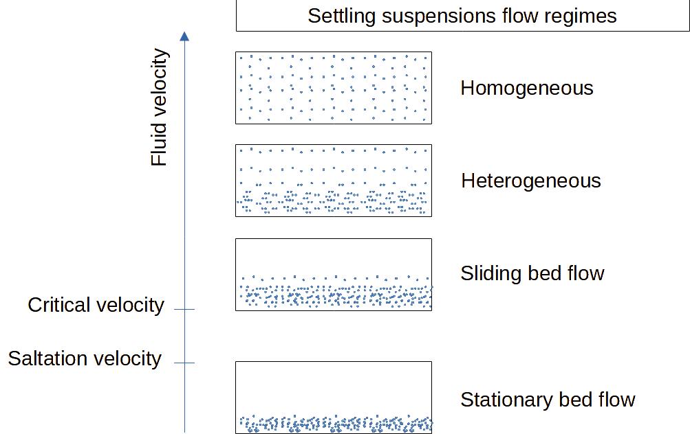
Settling suspensions (settling slurries) have the characteristic to separate easily in 2 phases, particles at the bottom and liquid at the top of a horizontal pipe, if the turbulence is not enough.
The more the fluid velocity is high and the flow turbulent, the more the suspension will appear homogeneous, although with large solid particles it may not be possible to avoid a gradient of concentration with more particles at the bottom of the pipe.
With a lower fluid velocity, the particles will start depositing at the bottom of the pipe forming an heterogeneous suspension. When the velocity is low enough there will be a layer of solids that will grow. As long the velocity is high enough, above a critical velocity, the layer will form a moving bed, but at even lower speed, below the so called saltation velocity, the bed of solid will become stationary (there is no more conveying of the solids then).
Top
5 Most Popular
1.
Pneumatic transport design guide
2. Ribbon
blenders
3. Powder mixing
4. Hoppers design guide
5. Measuring degree of
mixing
--------------
 --------------
Top 5 New
1.
Continuous Dry Mixing
2. Mixing speed
3. Mixer cycle time optimization
4. Batch / continuous mixing
comparison
5. Energy Savings
Figure 1 : settling suspensions flow regimes
Depending on the characteristics of the solids being transported, especially the size of the particles, it is more or less easy to keep the particles in suspensions in a low viscosity fluid. The following guide given by [Perry] can be used as a rule of thumb :
| Particle size diameter |
Suspension characteristics for horizontal pipes |
| < 10 microns | Usually fully suspended |
| 10-100 microns | Usually fully suspended with a concentration gradient |
| 100-1000 microns | Usually moved as sliding bed at the bottom of the pipe, may be fully suspended at high velocity |
| 1000-10000 microns | Transported as moving bed |
| >10000 microns | Cannot be suspended except if very light |
Typical velocity as given by [Perry] is 1 to 3 m/s
4.2 Pressure drop changes as a function of flow regime
For given solids particles, low viscosity liquid, and solids flowrate, the pressure drop is changing significantly with the fluid velocity and the flow regime.
The pressure drop is at a minimum typically in between sliding bed and heterogeneous flow, which means that it is industrially interesting to operate in those regimes in order to save energy. The pressure drop is higher once saltation has occurred because only a part of the pipe is available for the liquid. The pressure drop increases strongly for reaching homogeneous flow, and tends to be close to the fluid only pressure drop at high velocities.
For a same liquid velocity, the pressure drop is higher if the solids concentration increases.
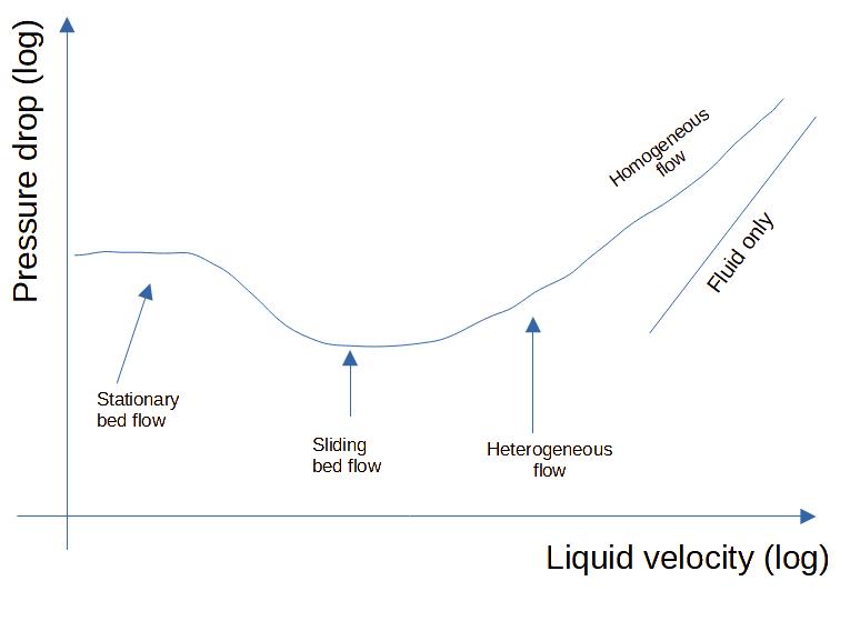
Figure 2 : Settling suspension
pressure drop profile as function of fluid velocity
In literature [Perry], the minimum transport velocity that allows to go from a sliding bed flow to an heterogeneous flow is often named VM2, the transition from heterogeneous flow to homogeneous flow is often called VM1.
- VM2 = transition velocity from sliding bed flow to heterogeneous flow
- VM1 = transition velocity from heterogeneous flow to homogeneous flow
The following correlations allow to calculate VM1 and VM2.
The minimum transport velocity VM2 can be estimated via the Durand equation :
VM2 = FL.[2.g.D.(s-1)]0.5
With :
VM2 = minimum transport velocity (switch from sliding
bed to heterogeneous suspension)
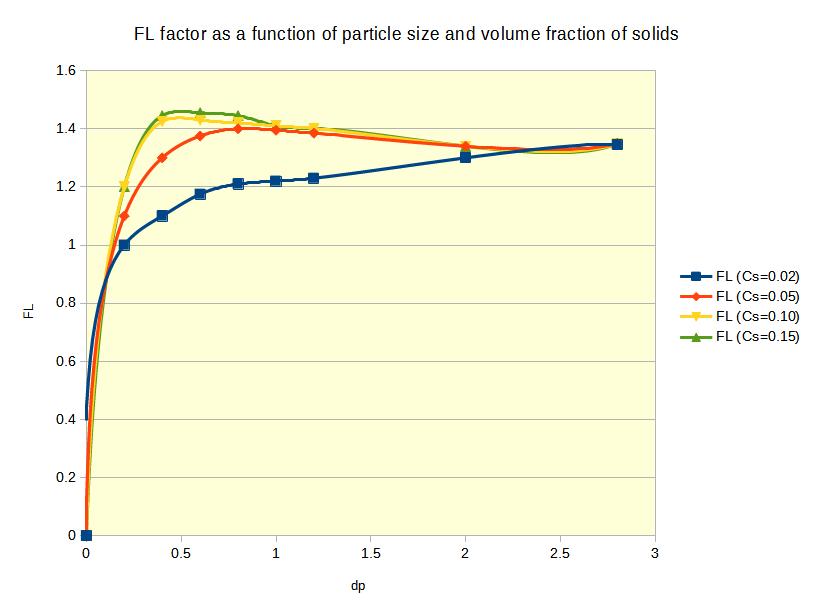
FL = Durand factor = 2.43*Cv1.3/Cd1.4
g = acceleration of gravity
s = ρs/ρl = ratio of solid to liquid density
Cv = solids concentration (in volume fraction)
Cd = single particle drag coefficient = 4/3*(g.dp.(s-1))/Ut
dp = particle diameter
Ut = single particle terminal settling velocity
FL can also be determined graphically (note this is an approximate graph, as we cannot reproduce the original).
The transition velocity for homogeneous flow VM1 can be estimated thanks to the following equation :

With :
VM1 = transition velocity from heterogeneous flow to
homogeneous flow
D = pipe diameter
Ds = particle diameter (85% in weight < Ds)
ρM = slurry mixture density
μ = liquid viscosity
s = ρs/ρl = ratio of solid to liquid density
4.3 Settling suspension pressure drop calculation
The pressure drop of a settling suspension flow in pipes is not straightfoward to calculate. There is also more correlations available for horizontal flow vs vertical flow.
4.3.1 Settling suspension pressure drop in horizontal pipes
It seems there are different correlations available but none is totally satisfactory, [Shamlou] is reporting correlations due to Newitt for particles having a size in between 2-600 microns, particle density in between 1.18-4.60 and volume solids fraction of up to 37%. Newitt is proposing different formula depending on the flow regime :
When velocity > 1800.g.D.Ut, the flow is homogeneous
Homogeneous flow : 
When velocity < 1800.g.D.Ut, the flow is heterogeneous
Heterogeneous flow : 
When velocity is < 17Ut, it is a sliding bed flow
Sliding bed flow : 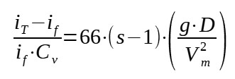
With :
iT = total head loss per unit of length due to the
flow of suspension
if = pipe frictional loss for the flow of liquid alone
= 2.ff.Vm2/(2g.D)
ff = Fanning friction factor for the fluid alone
Cv = solids concentration (in volume fraction)
s = ρs/ρl = ratio of solid to liquid density
g = acceleration of gravity
D = pipe diameter
Vm = mean suspension velocity
Ut = single particle terminal settling velocity
4.3.2 Settling suspension pressure drop in vertical pipes
Another correlation by Newitt et al. can be used to estimate the pressure drop of settling suspension flowing in a vertical pipe. The correlation was developped using solids of density 1.2 to 4.6 and having particle sizes in between 100 and 3800 microns.

With : iT = total head loss per unit of length due to
the flow of suspension
if = pipe frictional loss for the flow of liquid alone
= 2.ff.Vm2/(2g.D)
ff = Fanning friction factor for the fluid alone
Cv = solids concentration (in volume fraction)
g = acceleration of gravity
D = pipe diameter
Vm = mean suspension velocity
dp = particle diameter
5. Non Settling suspensions hydraulic conveying
Contrary to settling suspensions, non settling suspensions are more stable and can stay homogeneous even at low velocity or even in laminar flow. It is possible to achieve such suspensions by using very fine solids particles (<30 microns), or by increasing the viscosity of the fluid enough so that the settling velocity is very low.
5.1 Rheology of non settling suspensions
The interactions in between the particles and the fluid is leading to specific rheological behavior which are non Newtonian :
- Pseudoplastic (shear thinning)
- Dilatant (shear tickening)
- Bingham plastic
- Thixotropic
- Antithixotropic
- Viscoelastic
Those different rheological behaviors can be identified thanks to shear diagrams. To know more about non Newtonian fluid, you can refer to this MyEngineeringTools.com article : link.


5.2 Non settling suspensions pressure drop calculation
5.2.1 Rheological model
The apparent viscosity of non settling suspensions is not constant with the shear rate, it means a "unique" viscosity value cannot be used in calculations as it is the case for Newtonian fluids. It is necessary to approximate the complex rheology thanks to a model.
One of the most widely used model, which can represent relatively well pseudoplastic and dilatant suspensions is the power law model. When plotting the shear diagram through a logarithmic form it is indeed often a straight line. It is then possible to identify 2 parameters, K' and n' (slope) that can be used to model the fluid viscosity :
τ = K'.γn'
With :
τ = shear stress
γ = shear rate
n' = degree of non Newtonian behavior (0 < n' < 1 for
pseudoplastic materials ; n' < 1 for dilatant materials ; n' =
1 for Newtonian fluids)
K' = consistency index of the fluid
K' and n' can be calculated through experiments with capillary tubes viscosimeters, the apparent viscosity at a given shear rate can then be calculated.
5.2.2 Pressure drop calculation
As for settling suspensions, there are many different correlations proposed to calculate the pressure drop of non settling suspensions, those correlations have different levels of precisions so caution should be exerted when applying them.
As the viscosity is non Newtonian, it is necessary to define a generalized Reynold number for the fluid flow calculations :
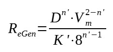
With :
ReGen = Generalized Reynolds number
D = pipe diameter
Vm = mean suspension velocity
n' = degree of non Newtonian behavior (0 < n' < 1 for
pseudoplastic materials ; n' < 1 for dilatant materials ; n' =
1 for Newtonian fluids)
K' = consistency index of the fluid
Laminar flow
In laminar flow, the generalized Reynolds number equation allows to have a simple expression to calculate the Fanning friction factor :
ff = 16 / ReGen
with :
ff = Fanning friction factor = (D.ΔP/4L)*(ρ.Vm2/2)2
It is then possible to estimate the pressure drop fairly directly.
Turbulent flow
The turbulent flow is much more complex and correlations with different degrees of accuracy and complexity have been developped.
Among the different correlations cited by [Shamlou], the following from Dodge and Metzner can be mentioned :

With :
fTS = turbulent friction factor for flow in smooth wall tubes
ReGen = Generalized Reynolds number
n' = degree of non Newtonian behavior (0 < n' < 1 for
pseudoplastic materials ; n' < 1 for dilatant materials ; n' =
1 for Newtonian fluids)
The calculations above do not take into considerations pipe singularities such as bends or fittings. For non Newtonian fluids, there are not much correlations developped. It seems that for fully turbulent flow, the behavior is similar to Newtonian fluids, however it is very much different in laminar flow. [Shamlou] as a 1st approximation is proposing to take 12 m equivalent length for 90 degrees bends.
6. Calculations in practice
As stated above, the correlations are not very precise, all the more that they usually have a very narrow validated range. It is thus crucial to use them only to sense check ideas but not for detail design. Detail design of a new installation, with an unknown slurry, should be based on experimental trials in a scale as close as possible to the future industrial application.
Source
[Perry] Perry's Chemical Engineer's Handbook, Section 6 Fluid Dynamics, page 6-31, McGraw-Hill, 2008