NEWS : Process Engineer's Tools is moving to a new address, www.MyEngineeringTools.com, click here to discover the site |
Shell - Tube Heat Exchanger : transfer coefficient on the shell
side
How to calculate the heat transfer coefficients on the shell side of a shell tube HX ? Bell Delaware method
Follow us on Twitter ![]()
Question, remark ? Contact us at powder.process@protonmail.com
| Section summary |
|---|
| 1. Flow pattern in
the shell of a shell-tube heat exchanger according to
Bell-Delaware |
| 2. Heat transfer on
the shell side of a shell tube heat exchanger (Bell
Delaware method) |
1. Flow pattern in the shell of a shell-tube heat exchanger
according to Bell-Delaware
The fluid flow on the shell side is complex. It has several components as several flow channels can develop, leading to different heat transfer coefficient. The Bell-Delaware method is actually based on the calculation of an ideal flow heat transfer coefficient that is then corrected by several coefficients accounting for non idealities.
The flow in the shell is modeled with 5 components :
- A : leakage in the clearance between tube and tube hole in a baffle
- B : main cross flow stream in the shell
- C : bypass stream in between the shell wall and the tube bundle
- E : leakage in between the shell wall and the baffle
- F : bypass steam in tube pass partitions
2. Heat transfer on the shell side of a shell tube heat
exchanger (Bell Delaware method)
The actual heat exchange coefficient hc is calculated from the ideal heat transfer coefficient he for pure cross flow in the tube bank. he is corrected by 4 factors :
hc = he.kch.kF.kBP.KRe
With :
hc = shell side heat transfer coefficient (W/m2.°c)
he = heat transfer coefficient for pure cross flow in the
tube bank - accounts for an ideal stream B (W/m2.°c)
kch
= correction factor for baffle cut (0.65 to 1.15)
kF = correction factor for baffle leakage effects (0.7
to 0.8) - accounts for streams A and E
kBP = correction factor for bundle bypass flow (0.7 to
0.9) - accounts for streams C and F
kRE = correction factor in laminar flow
As an order of magnitude, the combination of all correction factor is typically around 0.6, which means that a real shell tube heat exchanger will yield only 60% of the ideal heat exchange coefficient if there would be a perfect cross flow in the tube bank.
2.1 Calculation of the cross flow heat coefficient he
The Bell-Delaware method is defining he as :
he = J.C.GCT.Pr-2/3.(μ/μt)0.14

With :
he = heat transfer coefficient for pure cross flow in
the tube bank(W/m2.°c)
J = coefficient determined for an ideal bank cross flow
C = specific heat of the fluid in J/kg/K (m2/s2/K)
GCT = mass velocity (cross flow) (kg/m2/s)
Pr = Prandtl number (-)
μ = viscosity of the fluid at bulk temperature in Pa.s (kg/m/s)
μp = viscosity of the fluid a wall temperature in Pa.s
(kg/m/s)
2.1.1 Calculation of ReCT
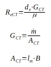
The Reynolds number of the cross flow stream is expressed the following way :

With :
ReCT = Reynolds of the pure cross flow stream across the
tube bank (-)
de = tube outside diameter (m)
μ = viscosity of the fluid at bulk temperature in Pa.s (kg/m/s)
GCT = mass velocity (cross flow) (kg/m2/s)
ACT = minimum cross sectional area within the tube field
(m2)
B = baffle spacing (m)
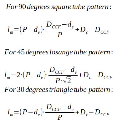
lm is calculated with the formula given afterwards (m)
lm depends on the geometry of the tube bank, which pattern is used.

With :
DC = Shell diameter
DCCF = tube bundle diameter (from most external tubes)
P = tube layout pitch
d = tube outside diameter
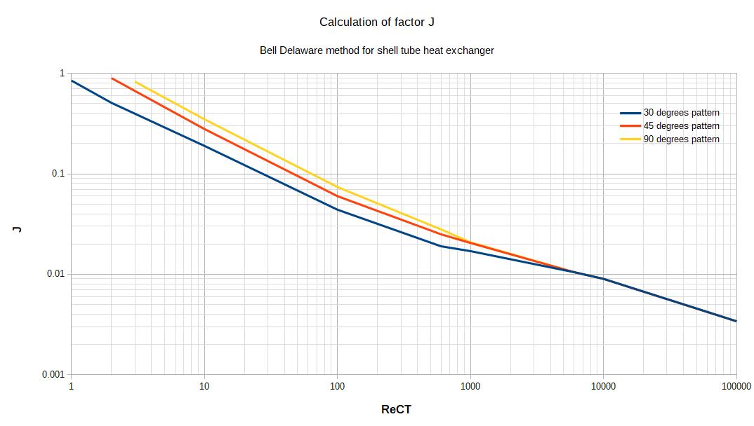
2.1.2 Calculation of J
J is determined thanks to an abacus, by knowing the tube bank geometry and calculating the Reynolds number of the cross flow stream.

2.1.3 Calculation of he
At this stage, all the factors have been defined and he can be calculated :
he = J.C.GCT.Pr-2/3.(μ/μt)0.14