NEWS : Process Engineer's Tools is moving to a new address, www.MyEngineeringTools.com, click here to discover the site |
Shell - Tube Heat Exchanger : calculation of correction
coefficients of Bell-Delaware method
Follow us on Twitter ![]()
Question, remark ? Contact us at powder.process@protonmail.com
| Section summary |
|---|
| 1. Correction
coefficients applied in Bell-Delaware method |
| 2. Calculation of
correction coefficients of the Bell-Delaware method |
| 3. Calculation of the heat transfer coefficient on the shell side of a shell tube heat exchanger |
1. Correction coefficients applied in Bell-Delaware method
The Bell-Delaware method allows to calculate the heat transfer coefficient of a Shell-Tube heat exchanger on the shell side. It is based on the application of correction coefficients to an ideal heat transfer coefficient on the shell side. Those coefficients are the following :
- kch = correction factor for baffle cut
- kF = correction factor for baffle leakage effects - accounts for streams A and E
- kBP = correction factor for bundle bypass flow - accounts for streams C and F
- kRE = correction factor in laminar flow
This page is detailing how to calculate each correction coefficient.
2. Calculation of correction coefficients of the Bell-Delaware
method
2.1 kch correction factor for baffle cut
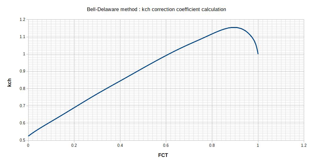
This correction factor is depending on the number of tubes that are located in cross flow (means they are covered by the baffle and the flow is forced through them). The factor FCT is then representing the fraction of the number of tubes in cross flow over the total number of tubes.

With :
DC = Shell diameter (m)
DCCF = tube bundle diameter (from most external tubes)
(m)
h = baffle cut (m)
The value of FCT is then used with the following Abacus to calculate kch :

2.2 kF correction factor
kF is accounting for leakages due to the bypass of the baffles. The flow can leak through the space around the baffle, or through the space in between the tubes and the baffles.
2.2.1 Leakage area AFC.ch in between the shell and the baffle

With :
DC = Shell diameter (m)
DCCF = tube bundle diameter (from most external tubes)
(m)
h = baffle cut (m)
2.2.2 Leakage area AFt.ch in between the tubes and the baffle

With :
de = tube outside diameter (m)
dtr = baffle hole diameter (m)
FCT as calculated in paragraph 2.1
2.2.3 Calculation of the total leakage area
The total leakage area is the sum of the leakage in between the baffle and the shell, and in between the baffle and the tubes.
AF=AFc.ch + AFt.ch
2.2.4 Calculation of kF
kF is determined according to the following abacus :

With AF as calculated in paragraph 2.2.3, AFc.ch as calculated in paragraph 2.2.1 and ACT as calculated here.
2.3 kBP correction factor
This correction coefficient accounts for tube bundle bypass. It depends on the number of sealing strips that are used in the heat exchanger.
An abacus given by Bell is also given for the calculation but different parameters must 1st be calculated.
2.3.1 Number of sealing strips
Sealing strips come by pairs. They are generally in between 1 to 4 pairs, the number of pairs is noted NDL.
2.3.2 Bundle bypass area ABP
ABP = (DC - DCCF)*B
DC = Shell diameter (m)
DCCF = tube bundle diameter (from most external tubes)
(m)
B = Baffle spacing (m)
2.3.3 Ratio of bundle bypass area to cross flow area
FBP = ABP / ACT = [(DC-DCCF)*B]/ACT
With :
DC = Shell diameter (m)
DCCF = tube bundle diameter (from most external tubes)
(m)
ACT as calculated here
2.3.4 Number of tube rows crossed between baffle tips in one baffle section
This value depends on the tube layout used.
- 90° layout : NCT = (Dc-2h)/P
- 45° layout : NCT = (Dc-2h)/(P√2/2)
- 30° layout : NCT = (Dc-2h)/(P√3/2)
With :
DC = Shell diameter (m)
P = tube layout pitch (m)
h = baffle cut (m)
2.3.5 Calculation of kBP
kBP is determined according to the following abacus by calculating the ratios NDL/NCT as well as the Reynolds.

2.4 kRE correction factor for laminar flow
In case the flow on the shell side is laminar, the dynamic of the fluid changes completely and an additional correction coefficient must be applied.
kRe = 1 if Re < 20 or Re > 100, in this case no
need to go through the calculation procedure given below.
2.4.1 Calculation of the baffles number
The number of baffle can be calculated by :
Nch = L/B - 1
With
L = tube length (m)
B = Baffle spacing (m)
2.4.2 Calculation of the number of tube rows in baffle window
This value depends on the tube layout used.
- 90° layout : NOF = [h-(Dc-DCCF)/2]/P
- 45° layout : NOF = [h-(Dc-DCCF)/2]/(P√2/2)
- 30° layout : NOF = [h-(Dc-DCCF)/2]/(P√3/2)
With :
DC = Shell diameter (m)
DCCF = tube bundle diameter (from most external tubes)
(m)
P = tube layout pitch (m)
h = baffle cut (m)
2.4.3 Number of tube rows crossed between baffles
NCT + NOF
2.4.4 Calculation of kRE
kRE is calculated thanks to 2 abacus. The 1st abacus allows to get an intermediary coefficient k*RE and the second abacus, using k*RE, allows to calculate kRE.


3. Calculation of the heat transfer coefficient on the shell side of a shell tube heat exchanger
The coefficient calculated above can be used to calculate the heat transfer coefficient the following way :